Universal Serial Bus Type-C Connectors , USB Type-C connector 4-Axis Continuity Test


- Product Details
- Inquiry
Product Description
Universal Serial Bus Type-C Connectors , The USB Type-C connector 4-Axis Continuity Test
D 4-Axis Continuity Test
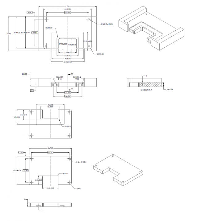
The USB Type-C connector family shall be tested for continuity under stress using a test fixture shown in
Figure E or equivalent.
Figure D-1 Example of 4-AxIs Continuity Test Fixture
Plugs shall be supplied with a representative overmold or mounted on a 2-layer printed circuit board (PCB) between 0.8 mm and 1.0 mm thickness as applicable. A USB Type-C receptacle shall be mounted on a 2-layer PCB between 0.8 mm and 1.0 mm thickness. The PCB shall be clamped on three sides of the receptacle no further than 5 mm away from the receptacle outline. The receptacle PCB shall initially be placed in a horizontal plane, and a perpendicular moment shall be applied to the plug with a 5 mm ball tipped probe for a period of at least 10 seconds at a distance of 15 mm from the mating edge of the receptacle shell in a downward direction, perpendicular to the axis of insertion. See Table D-1 for the force and moment to be applied.
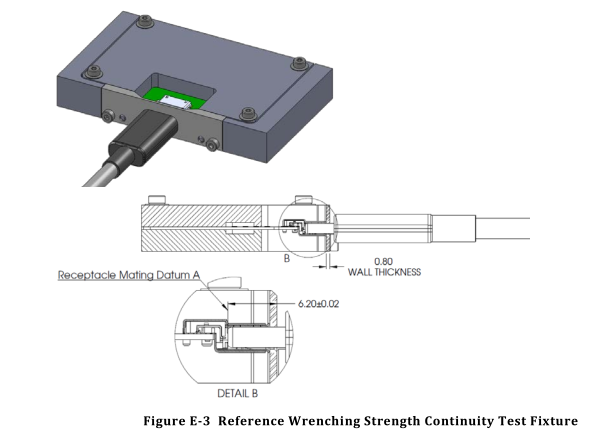
Figure E-3 Reference Wrenching Strength Continuity Test Fixture
Inquiry
Next: Jointed test probe for equipment likely to be accessible to children | IEC 62368 -1-Figure V.1


