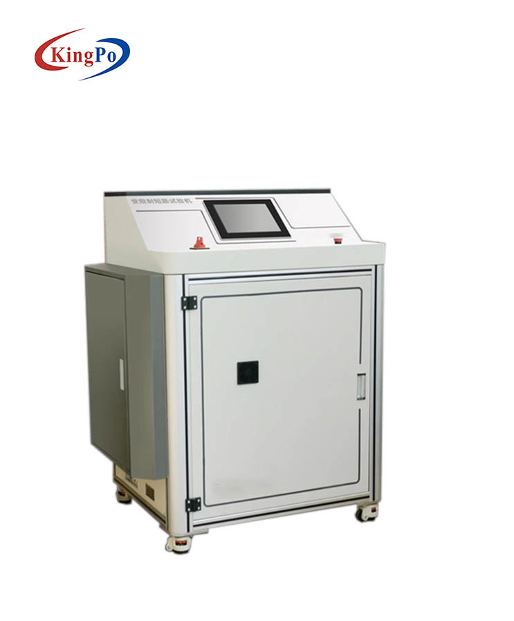
IEC62368 Annex R Limited Short-Circuit Tester ,Current Generator 1500 A
- Product Details
- Inquiry
Product Description
The restricted short circuit test device is applicable to the test of protective grounding conductor and current protection circuit breaker 1500A. The purpose of this test device is to verify that the protective connecting conductor used in the circuit protected by the device with a rated value not exceeding 25A is compatible with the fault current allowed by the overcurrent protection device, and to test the integrity of additional safety protection through such tests.
Meet the requirements of Clause 5.6.4.1&5.6.5.1 and Appendix R in IEC62368-1:2018 and GB 4943.1-2022 Audio Video, Information Technology and Communication Technology Equipment – Part 1: Safety Requirements.
Product test object: audio, video, information and communication technology equipment
Equipment principle:
The limited short circuit test device system uses the energy storage device to realize the instantaneous high current test. The discharge time and initial voltage can be set. After the discharge is completed, it will automatically charge for the next round of test. During the test, the discharge current will be recorded to generate the current time curve.
Equipment characteristics:
1. Meet the test requirements of IEC62368-1:2018, EN62368-1:2019 and GB4943.1-2022 standards;
2. 15 inch super large true color touch LCD, high-speed thermal printer;
3. High precision sensor and high-performance 14 bit AD acquisition chip;
4. Man machine dialogue full keyboard operation mode, and the whole process of intelligent work;
5. Optional automatic current rise test, manual current rise test and impact quick break test, flexible and simple operation;
6. Real time display of output current and time results is intuitive;
7. Perfect over-current protection, arbitrary setting of target output current value, current upper limit and current withstand time;
8. With grounding detection function and zero return detection function, the test can be carried out after the grounding and zero return are determined, which is safe and reliable;
9. Approximation type current raising algorithm, when the set target output current is reached, the current tolerance timing will be automatic, and the motor will return to zero automatically after the timing is completed;
10. If the upper limit of the set output current is exceeded, the motor will automatically return to zero and give an audible and visual alarm;
11. Sophisticated anti-interference design of software and hardware, multiple anti-interference means, adapt to harsh electromagnetic environment;
12. It can be equipped with remote communication, door interlock alarm, opening voltage verification interface, etc.
Main technical parameters:
1. Control mode: PLC control+touch screen man-machine interface intelligent operation;
2. Test station: 1 station;
3. Test range:<25A;
4. Limit current: ≥ 1500A (customizable);
5. Discharge time: 5~100ms can be set;
6. Test mode: AC and DC switchable test;
7. Discharge voltage: customized according to customer requirements;
8. Test time: touch screen can be set according to standard requirements;
9. Standard configuration: power supply DC power supply, over-current protection device, waveform curve oscilloscope provided by customers, configured with 2.5 square meters, 4 3m test lines;
10. Test function: discharge voltage and limit protection time can be set, with overvoltage and overcurrent protection function;
11. Safety protection: it has the function of abnormal shutdown alarm, and the connection is made of insulating materials;
12. Overall dimension: W1250 × D960 × H1650mm;
13. Equipment power supply: AC220V 50Hz.
Feature:
First charge the battery inside the device, discharge it to the set voltage, and then realize the instantaneous high current test. The discharge time and voltage can be set. After the discharge is completed, it will automatically charge for the next test. The discharge current is recorded during the test, and the system will automatically generate a current-time curve.
Function:
▪ automatic/manual features;
▪ discharge voltage and limit protection time can be set;
▪ waveform curve analysis function;
▪ with overpressure overcurrent protection function;
▪ operation interface (as shown below)
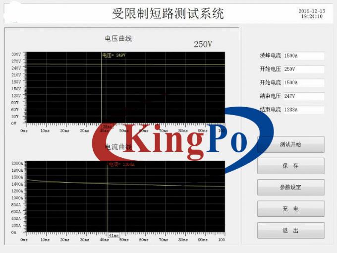
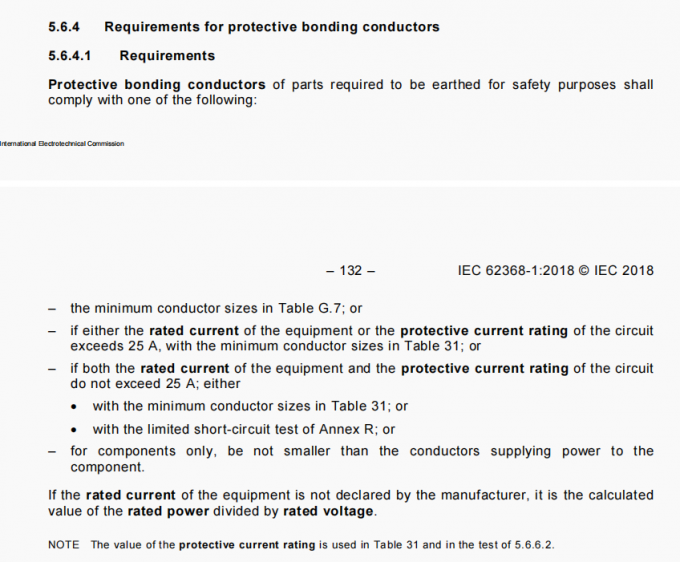
Table 31-Minimum protective bonding conductor size of copper conductors
| Smaller of the rated current of the equipment or the protective current rating of the circuit under consideration A up to and including | Minimum conductor sizes | |
| Cross-sectional area mm2 | AWG [cross-sectional area in mm2] | |
| 3 | 0,3 | 22 [0,324] |
| 6 | 0,5 | 20 [0,519] |
| 10 | 0,75 | 18 [0,8] |
| 13 | 1,0 | 16 [1,3] |
| 16 | 1,25 | 16 [1,3] |
| 25 | 1,5 | 14 [2] |
| 32 | 2,5 | 12 [3] |
| 40 | 4,0 | 10 [5] |
| 63 | 6,0 | 8 [8] |
| 80 | 10 | 6 [13] |
| 100 | 16 | 4 [21] |
| 125 | 25 | 2 [33] |
| 160 | 35 | 1 [42] |
| 190 | 50 | 0 [53] |
| 230 | 70 | 000 [85] |
| 260 | 95 | 0000 [107] |
| kcmil [cross-sectional area in mm²] | ||
| 300 | 120 | 250 [126] |
| 340 | 150 | 300 [152] |
| 400 | 185 | 400 [202] |
| 460 | 240 | 500 [253] |
| NOTE AWG and kcmil sizes are provided for information only. The associated cross-sectional areas have been rounded to show significant figures only.AWG refers to the American Wire Gage and the term “cmil” refers to circular mils where one circular mil is equal to (diameter in mils)2.These terms are commonly used to designate wire sizes in North America. | ||


